In today’s rapidly evolving manufacturing industry, precision and efficiency are paramount. One crucial element that plays a significant role in achieving accurate machining is the 3 jaw chuck CAD model. This blog post will delve into the various aspects of this essential tool, its benefits, applications, and how it revolutionizes the manufacturing process.
Section 1: Understanding the 3 Jaw Chuck CAD Model
A 3 jaw chuck CAD model refers to a computer-aided design representation of a 3 jaw chuck. A 3 jaw chuck is a gripping device used in machines to securely hold and rotate workpieces during machining processes. CAD modeling allows engineers and manufacturers to design, simulate, and analyze the chuck’s performance before its physical production, ensuring optimal functionality and precision.
Section 2: Benefits of Utilizing a 3 Jaw Chuck CAD Model
The utilization of a 3 jaw chuck CAD model offers numerous advantages to manufacturers:
1. Enhanced Precision: CAD modeling enables engineers to fine-tune the chuck’s design, ensuring precise gripping and alignment of workpieces. This accuracy translates into superior machining results, reducing errors and enhancing overall quality.
2. Time and Cost Efficiency: By simulating the chuck’s performance virtually, manufacturers can identify and rectify any potential issues before physical production. This significantly reduces material waste, minimizes downtime, and saves costs associated with rework.
3. Customization and Adaptability: CAD modeling allows for the creation of custom 3 jaw chuck designs tailored to specific machining requirements. Manufacturers can optimize chuck designs to accommodate different workpiece sizes, shapes, and materials, enhancing versatility in manufacturing processes.
Section 3: Applications of 3 Jaw Chuck CAD Models
The versatility of 3 jaw chuck CAD models extends to various machining applications, including:
1. Turning Operations: 3 jaw chucks are extensively used in lathe machines for turning cylindrical workpieces. CAD modeling ensures precise alignment and gripping, enabling accurate and smooth rotation during the machining process.
2. Milling and Drilling: 3 jaw chuck CAD models find applications in milling and drilling operations, providing a secure grip on workpieces to withstand the forces exerted during these processes. This ensures stability, accuracy, and repeatability, resulting in high-quality machined parts.
3. Grinding and Finishing: In grinding and finishing operations, precision is paramount. CAD modeling of 3 jaw chucks allows for meticulous alignment, ensuring optimal surface finishes and dimensional accuracy.
Section 4: Advancements in 3 Jaw Chuck CAD Modeling Technology
As technology continues to advance, so does the art of CAD modeling for 3 jaw chucks. Recent developments have led to the incorporation of advanced features such as:
1. Real-Time Simulation: Modern CAD software enables real-time simulation of chuck behavior, allowing engineers to assess the chuck’s performance under various operating conditions. This aids in identifying potential issues and optimizing design parameters for superior results.
2. Material Analysis and Optimization: CAD modeling tools now offer material analysis capabilities, allowing manufacturers to evaluate chuck performance based on different materials’ physical properties. This data helps optimize chuck designs for increased durability and efficiency.
3. Integration with Manufacturing Systems: CAD models of 3 jaw chucks can be seamlessly integrated into manufacturing systems, enabling real-time monitoring, feedback, and adjustments. This integration streamlines the manufacturing process, ensuring accuracy and efficiency from design to production.
Conclusion:
The 3 jaw chuck CAD model is an invaluable tool that revolutionizes manufacturing processes, providing enhanced precision, time and cost efficiency, and customization. From turning operations to grinding and finishing, the CAD model’s versatility finds applications across various machining processes. As technology advances, CAD modeling for 3 jaw chucks continues to evolve, offering real-time simulation and seamless integration with manufacturing systems. Embrace the power of the 3 jaw chuck CAD model and unlock new levels of precision in your manufacturing endeavors.
We hope you found this blog post informative and insightful. Have you had any experience with 3 jaw chuck CAD models? Feel free to share your thoughts, questions, or experiences in the comments section below.
3 jaw chuck | 3D CAD Model Library | GrabCAD
Mar 28, 2016 … 3 jaw chuck with detail you can turn the key of chuck its really work:-) – grabcad.com

3 jaw – Recent models | 3D CAD Model Collection | GrabCAD …
The GrabCAD Library offers millions of free CAD designs, CAD files, and 3D models. Join the GrabCAD Community today to gain access and download! – grabcad.com
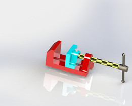
▷ 3 jaw chuck 3d models 【 STLFinder 】
This is a small 3-jaw scroll chuck. It’s 92mm in diameter and has a 1″ NPT thread. The parts have been designed to print without supports, in the orientations … – www.stlfinder.com

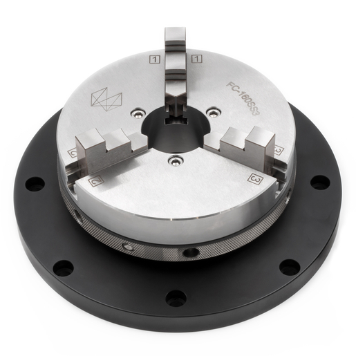
3-Jaw Chuck with Flange (Stainless Steel / D = 160 mm)
Further information can be found in the CAD-file. Please note: This chuck is not compatible with the integrated rotary table iRT 4 HD. Specification. Outside … – shop.hexagonmi.com
Free 3D CAD Models, 2D Drawings, and … – 3D ContentCentral
Results 1 – 10 of 22 … chuck. Title. 6.25″ 3-Jaw Lathe Chuck. Description. 6.25″ Lathe Chuck … Chuck and the Jaws by specifying this assembly model. It has … – www.3dcontentcentral.com
isel Germany AG – Free CAD models – Clamping chuck – TraceParts
Manufacturer, isel Germany AG. Description, Three-jaw chuck ø65 with flange for MD1 – ZR20 – ZD30. Part number, 269060 2065 … – www.traceparts.com
Build Thread JET GHB-1340A CNC Conversion (CAD Model link)
Jun 16, 2016 … The 3 jaw chuck and faceplate taper were NOT made to the right size, they would not seat against the back of the D1-4 spindle. This made … – www.cnczone.com
Need 3D Bison Chuck model!
Hi, anyone know where I can download a SW model of a 3 jaw chuck? The exact … i used a chuck cad model in the model of a lathe i put in 3dcontentcentral. – www.cnczone.com
CAD for Self Centering Chuck for MR-1: Hold Round Stock – MR-1 …
Sep 20, 2023 … Great way to add the ability to hold all sorts of round, square, and hexagonal parts- much better than a 3 jaw, and worth the extra dough. If … – forum.langmuirsystems.com
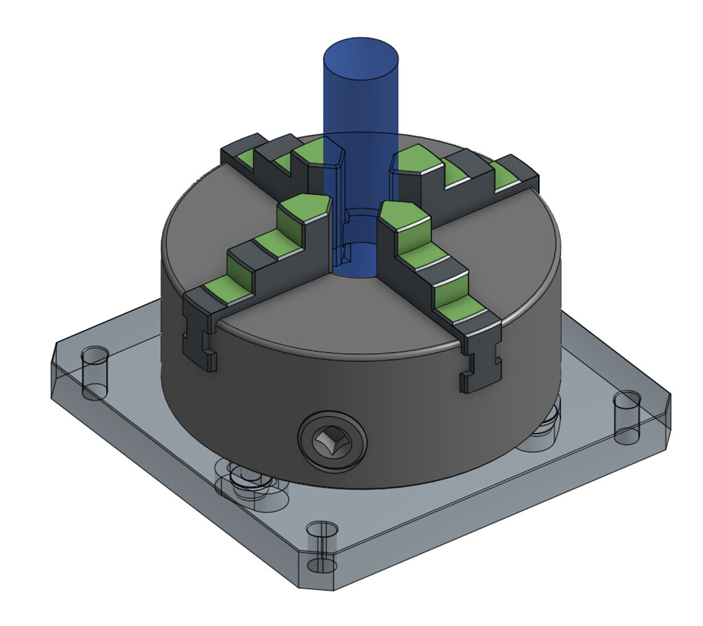
Car 3 Point Turn Cad Block
Car 3 Point Turn CAD Block: Enhancing Precision and Efficiency in Vehicle Design In today’s rapidly evolving automotive industry precision and efficiency are paramount in vehicle design. CAD (Computer-Aided Design) plays a vital role in creating accurate and detailed blueprints ensuring that every a – drawspaces.com
Official SOLIDWORKS Community – MySolidWorks
… Chuck and the Jaws by specifying this assembly model. 3D ContentCentral. 5 years ago. Lathe Chuck Assembly, 3-Jaw Scroll Type – 8 inch. 8″ scroll type lathe 3- … – my.solidworks.com