Welcome to this comprehensive blog post on Logic Circuit Draw, an essential tool that empowers digital design enthusiasts to create complex and efficient electronic circuits. Whether you’re a seasoned engineer or a curious beginner, this article aims to provide you with a thorough understanding of Logic Circuit Draw and its practical applications. So, let’s dive into the world of logic circuits and explore the wonders of Logic Circuit Draw!
I. Understanding Logic Circuits:
Logic circuits serve as the fundamental building blocks of modern digital systems. In this section, we will delve into the basics of logic circuits, including their components, functioning principles, and their significance in today’s technological landscape. By grasping these concepts, you will be able to appreciate the true power of Logic Circuit Draw.
II. Introducing Logic Circuit Draw:
Logic Circuit Draw is a user-friendly software that enables users to design digital circuits using a graphical interface. This section will acquaint you with the key features, functionalities, and advantages of Logic Circuit Draw. From the ease of use to the vast library of predefined components, you’ll discover how this software simplifies the process of designing and simulating logic circuits.
III. Step-by-Step Guide to Creating a Logic Circuit:
To help you get started, this section provides a step-by-step guide on how to create a logic circuit using Logic Circuit Draw. From selecting components to connecting them and simulating the circuit, you’ll gain hands-on experience in circuit creation. We will also explore various design techniques, such as combinational and sequential logic, enabling you to construct intricate circuits with ease.
IV. Advanced Features and Simulation Capabilities:
Logic Circuit Draw offers advanced features, such as the ability to perform complex simulations and analyze circuit behavior. In this section, we’ll delve into these capabilities, including how to use built-in simulation tools, analyze timing diagrams, and troubleshoot circuit issues. By harnessing these advanced features, you can confidently design and optimize circuits for various applications.
Conclusion:
As we wrap up this exploration into the world of Logic Circuit Draw, we hope you’ve gained valuable insights into the software’s capabilities and the importance of logic circuits in digital design. Whether you’re a hobbyist, a student, or a professional, Logic Circuit Draw can greatly enhance your ability to create, simulate, and refine digital circuits.
We encourage you to download Logic Circuit Draw and embark on your own circuit design journey. Unleash your creativity and explore the limitless possibilities of digital design. If you have any questions, experiences, or thoughts to share, we would love to hear from you! Leave a comment below and let’s continue the discussion.
Thank you for joining us on this adventure into the realm of Logic Circuit Draw. Happy designing!
Word Count: 370
technical drawing – How to make my logic circuit drawn by circuitikz …
Nov 8, 2012 … Here is a first approach to a smaller logic circuit, with more compact positioning, and colored label text. – tex.stackexchange.com

Logic circuit for (p ∧ q) → r , how do I draw the if statement …
May 11, 2019 … How do I draw the logic circuit for (p ∧ q) → r ? I send p and q through and AND gate and get p ∧ q, but what follows next, if I am only … – math.stackexchange.com

I am looking for a program that can draw digital logic circuit like this …
Jul 31, 2022 … 15 votes, 10 comments. 693K subscribers in the AskElectronics community. A subreddit for practical questions about component-level … – www.reddit.com
circuitikz – How to draw a big logic circuit with many inputs in latex …
Mar 18, 2019 … First of all welcome to TeX.SE, from next time please show us what you have tried so far. We generally don’t prefer do-it-for-me class of … – tex.stackexchange.com
Logic Circuit Draw
1. Draw a block diagram truth table and logic circuit of … Draw a block diagram truth table and logic circuit of a 16 x 1 multiplexer and explain its working principle. 10 Mark question | Asked in Digital Logic 2065 Solution www.collegenote.net Boolean Expression To Logic Circuit Converter Online – drawspaces.com

Drawing logical circuit for a simplified boolean expression – Stack …
Apr 12, 2020 … … draw the logical circuit when the simplified expression has only one variable? Any help is appreciated. Thanks. EDIT: I used AND gate and … – stackoverflow.com

Draw Logic Circuits with Fanout Branches using python’s …
Mar 5, 2022 … Schemdraw’s logicparse module isn’t smart enough to do that (yet). You’d have to draw it manually, something like this: with schemdraw. – stackoverflow.com
Logic Gates Draw
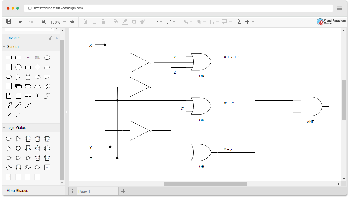
Logic Gate Online Drawing Logic Diagram Software Need to draw logic gate diagrams? Looking for a logic circuit tool? Visual Paradigm’s logic diagram tool features a handy diagram editor that allows you to … online.visual-paradigm.com Logic.ly Logic.ly. Please activate JavaScript to run Logic.ly in – drawspaces.com
Logic.ly
Logic.ly. Please activate JavaScript to run Logic.ly in your web browser. – logic.ly
Logic Diagram Software
Need to draw logic gate diagrams? Looking for a logic circuit tool? Visual Paradigm’s logic diagram tool features a handy diagram editor that allows you to … – online.visual-paradigm.com